Summary
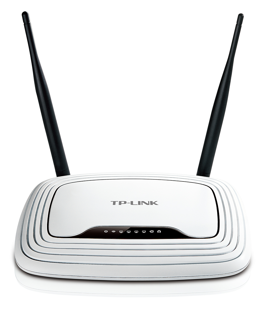
The TL-WR841N(D) v8.x is a dirty cheap router. It has:
- 535MHZ MIPS AR9341 SoC with GPIO multiplexing
- 4MByte Flash / 32MByte RAM
- OpenWRT capability
- JTAG pin header with 4 GPIOs easy to use
- only 15 Euro
This site is dedicated for hardware extension to this router
CAN Interface

This site describes a CAN interface directly connected to the JTAG header.
The OpenWRT images includes all bins to build up SocketCAN interface - except the
PIC firmware which needs to be loaded externally due to different licensing.
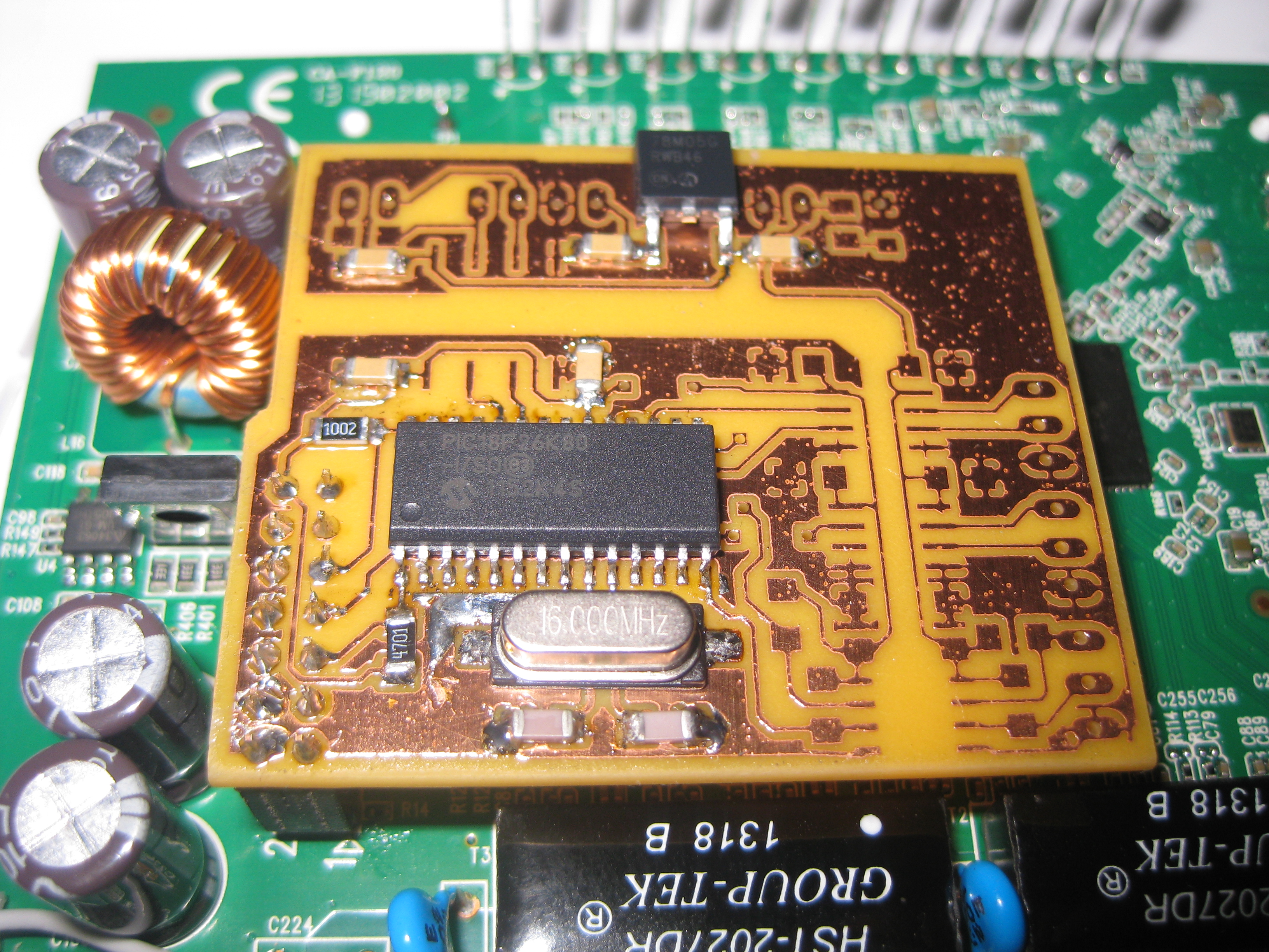
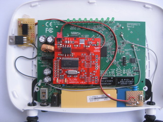
Hardware
The heart of the interfac is the PIC18F25K80 (PIC18F26K80 works also) which translates the CAN to serial data (SLCAN) and vice versa.
A TI ISO1050 tranceiver connects the PIC to the CANBus.
Due to the glavanic isolation you need to provide an external 5V source or use the build in 7805 linear voltage regulator and feed
it with a 7V to 30V source.
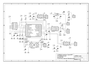
BOM (CAN only)
All R,C LEDS are SMD 1206
R1      4k7 Ohm
R2      120 Ohm
R7      270 Ohm
R8      10k Ohm
R9-10   220 Ohm
C1,C2    22pf
C3-C7   100nf
Q1      16MHz Crystal
LED1    LED green
LED2-3  LED yellow
IC1     PIC18F25K80-ISO or PIC18F26K80-ISO
IC2     TI ISO1050 DUBR
U$1	MC 78M05 CDTG
IC3 to IC5 are not needed for the CANBus - they are for future use.
You could use a breadboard to build or get PCBs here:
Dirty PCBs
Installing the 14 pin header on the router is a little bit tricky - I use a medecine needle with a 0.9mm diameter to get rid
of the solder.
Heat up the pad from the buttom with your solder iron (min 60W) and put the needle from top carefully thru the hole while twisting
a little bit.
The PCB also needs 3V3 - you can find it on the back at TP1. Use a wire and connect it to pin 14 of the JTAG pin header.
Software
Todo: describing OpenWRT first installation
Upgrade from original Software
Sysupgrade OpenWRT
The OpenWRT uses two parts provided by Darron Broad:
- PIC Programmer
- SLCAN Firmware
- SLCAN firmware source code
IMHO the clever part of this setup is that the GPIOs first work as programmer and afterwards as serial interface.
After setup (only need to be done once) you have a working SocketCAN interface:
Progamming firmware
root@ar9341:~# cd .pickle

root@ar9341:~/.pickle# ./pic-flash.sh
set GPIO3 as GPIO
set GPIO0 as GPIO

root@ar9341:~/.pickle# show-gpio | head -5
  seems to be a WR841N v8 with AR9341 Revision 3
   JP2 pin 9 GPIO00 O l GPIO
   JP2 pin 3 GPIO01 I l GPIO
   JP2 pin 5 GPIO02 O h GPIO
   JP2 pin 7 GPIO03 I h GPIO

+root@ar9341:~/.pickle# p16 lvp id
[000000] [PROGRAM]     8000 WORDS (0400 ROWS OF 0020 WORDS)
[200000] [IDLOCATION1] FF .
[200001] [IDLOCATION2] FF .
[200002] [IDLOCATION3] FF .
[200003] [IDLOCATION4] FF .
[200004] [IDLOCATION5] FF .
[200005] [IDLOCATION6] FF .
[200006] [IDLOCATION7] FF .
[200007] [IDLOCATION8] FF .
[300000] [CONFIG1]     1214
[300002] [CONFIG2]     2869
[300004] [CONFIG3]     8100
[300006] [CONFIG4]     0081
[300008] [CONFIG5]     C00F
[30000A] [CONFIG6]     E00F
[30000C] [CONFIG7]     400F
[3FFFFE] [DEVICEID]    6124 DEV:309 REV:04 PIC18F26K80
[F00000] [DATA]	       0400 BYTES
The firmware (500kBaud UART 250kBaud CAN)
is licensed under CC BY-NC-SA 4.0. This is different to the OpenWRT GPL(2/3) so it can't be included.
Nevertheless you can download it easily:
root@ar9341:~/.pickle# wget http://lnxpps.de/openwrt/wr841/bin/can-can_uart500_can250.hex

root@ar9341:~/.pickle# p16 lvp p can-can_uart500_can250.hex
Total: 854

root@ar9341:~/.pickle# p16 lvp v can-can_uart500_can250.hex
Total: 854 Fail: 0
Reconfigure pins to use as second UART
root@ar9341:~/.pickle# ./ser_setup.sh
GPIO input/output register
18040000:  00030302
set GPIO3 as input
set GPIO0 as output
set GPIO3 as UART1_RD
set GPIO0 as UART1_TD
set GPIO0 Output
18040000:  0003030a
set GPIO0 as UART1_TD
GPIO 2 on

root@ar9341:~/.pickle# show-gpio | head -5
  seems to be a WR841N v8 with AR9341 Revision 3
   JP2 pin 9 GPIO00 O - UART1_TD
   JP2 pin 3 GPIO01 I l GPIO
   JP2 pin 5 GPIO02 O h GPIO
   JP2 pin 7 GPIO03 I - UART1_RD
CAN interface configuration
root@ar9341:~/.pickle# cd
root@ar9341:~# slcand -S500000 ttyATH0 can0
root@ar9341:~# ifconfig can0 up
...
root@ar9341:~# ifconfig can0
can0      Link encap:UNSPEC  HWaddr 00-00-00-00-00-00-00-00-00-00-00-00-00-00-00-00
          UP RUNNING NOARP  MTU:16  Metric:1
          RX packets:21763 errors:0 dropped:0 overruns:0 frame:0
          TX packets:28363 errors:0 dropped:0 overruns:0 carrier:0
          collisions:0 txqueuelen:10
          RX bytes:156877 (153.2 KiB)  TX bytes:105633 (103.1 KiB)

root@ar9341:~# ip -s -d link show can0
6: can0:  mtu 16 qdisc fq_codel state UNKNOWN mode DEFAULT group default qlen 10
    link/can  promiscuity 0
    RX: bytes  packets  errors  dropped overrun mcast
    156877     21763    0       0       0       0
    TX: bytes  packets  errors  dropped carrier collsns
    105633     28363    0       0       0       0
You only need to programm the PIC once. After every restart the setup it done autmatically (TODO: not ready yet).
The image also contains software to test the CANBus, e.g.:
candump -tA -xe can0,0:0,#FFFFFFFF
shows any traffic on the CANBus. There are other tools included like cansend, cangen, and canbusload (slightly modified for microsecond resolution) from the CAN-Utils.
Example using the interface
can2eth shows how easy it can be used. The code takes CAN frames
and generates network packets and send it to the broadcast address on UDP port 7654. The other way arround there is a UDP
socket on port 7655 will accept network packets and put it on the CANBus.
TODOs
- write extended firmware to setup different baudrates on the fly
- I2C and RS485
Technical note
There are many sites (like these on my server here) describing the use of Microchips MCP2515 SPI CAN controller. The MCP2515
works fine - in fact there are some quirks but they are described in the Erratra. But the SPI interface is a challenge
for an OS like Linux. Normal OSes don't guarantee response time to exceptions like the interrupt form an external controller.
Due to interrupt latency there might be CAN frames interchanged or lost or more worse the kernel module might hang.
MCP2515 SPI interface is able to work at 10MHz - this looks enough to serve a CANBus even at 1MHz, but to get a single
CAN frames out of the controller you have ask for the buffer where the CAN messages is saved first. So you need to setup
some SPI sequences. The Linux kernel does have a fancy SPI driver using work-queues. But this increases the latency
even more. SPI sequences might wait for a long time.
For using SPI a hardware SPI is recommend. The AR9341 SoC on the WR841N v8.x provides a hardware SPI interface, but it
is shared with the flash. Any access to the flash memory will increase the latency even more.
The approach described above is different: The PIC MCU receives CAN frames and sending it directly to the UART. The
controller does not need to wait until the host request the data. So the PIC buffers are cleared immediatly.
The build in FIFOs of host systems will buffer the packets and that leads to better performance even with the ASCII
overhead.
CAN-CAN was written by Darron Broad in assembler and is greatly optimized. The code is able to translate more than 5000
CAN frames (test with extended frames and DLC8) to ASCII every second - this is more than a completely 500kbaud saturated CANBus would carry. This ouperforms many selfmade adapters and even some commercial ones.
Reduced to the max
Impressum: