Smallest Rocrail Server ever ?!
Consider using CAN-CAN Interface
Cheap, fast and reliable !
Sunnary:
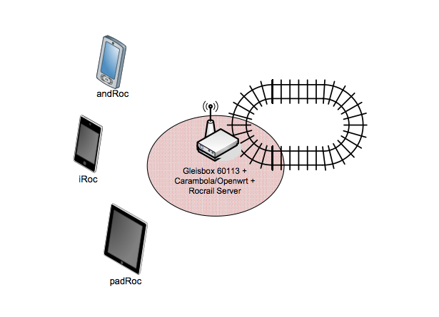
After building a "CAN Ethernet Bridge" I wanted to go one step further. How small can a Rocrail server be ? What about integrating all necessary parts controlling choo-choos into one device ?
The functionality is partly the same as the Gateway from the Maerklin CS2, but the Maerklin App doesn't work (yet).
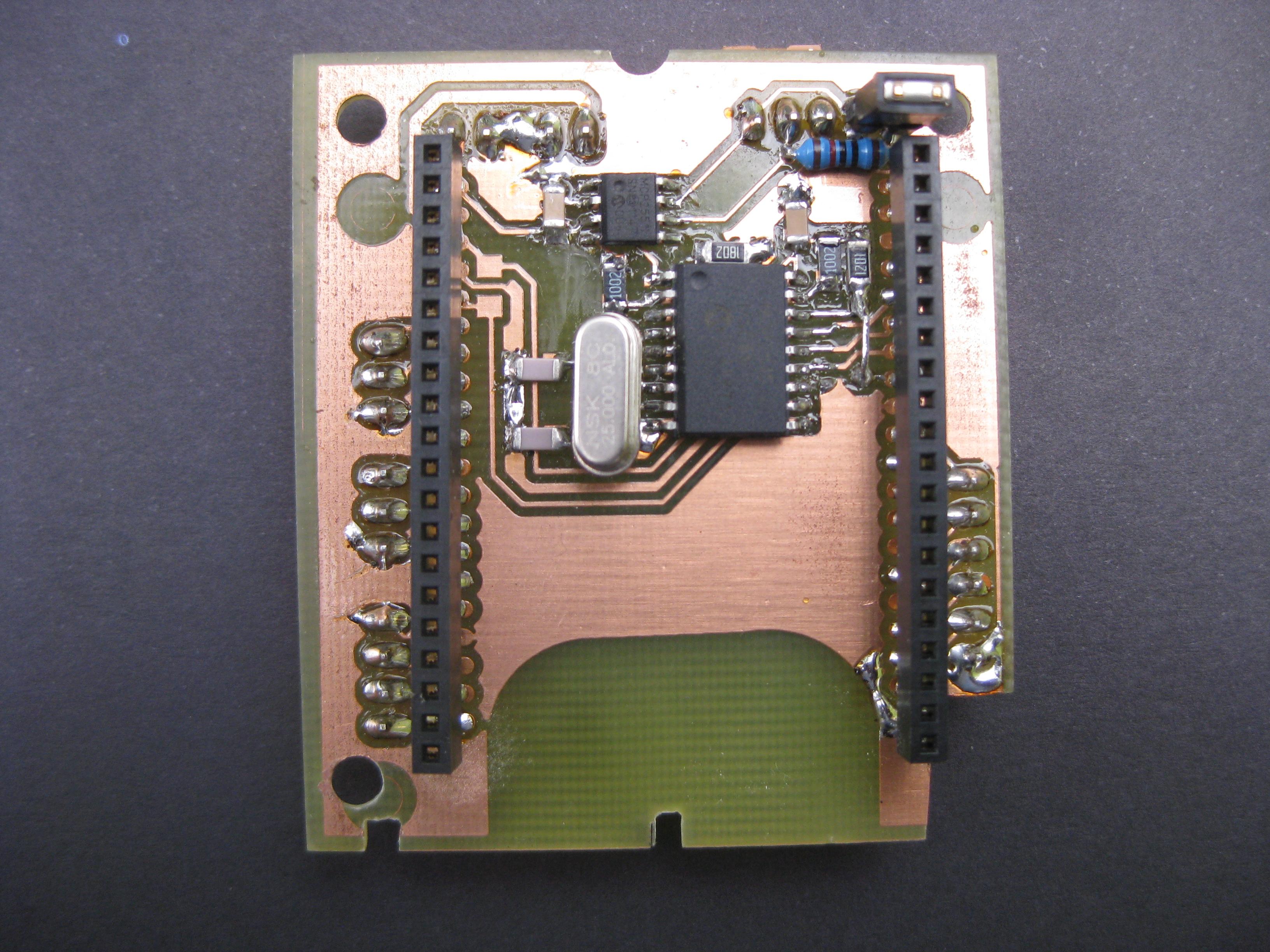
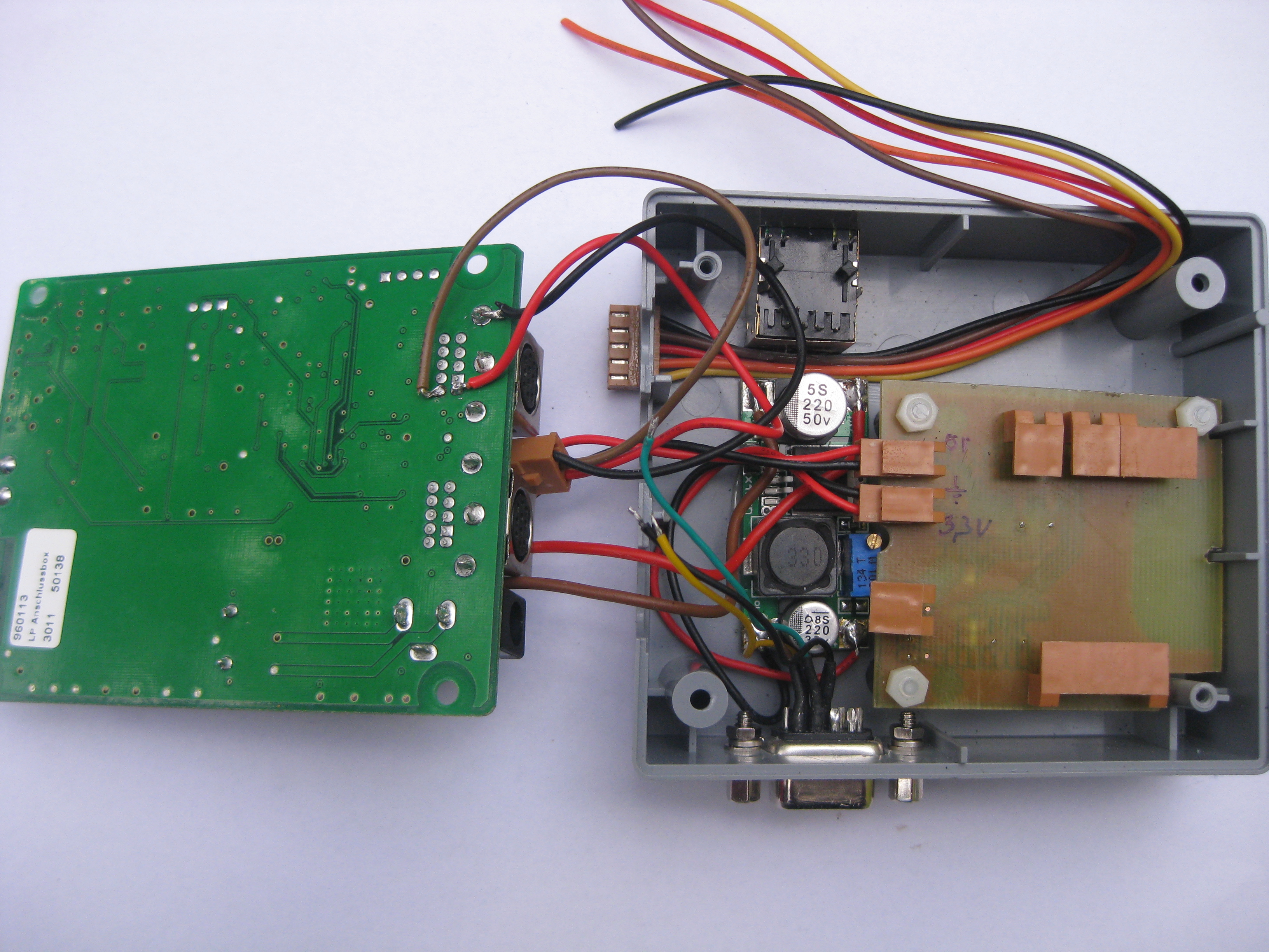
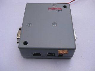
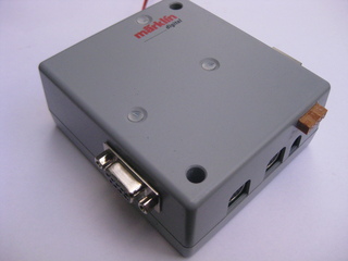
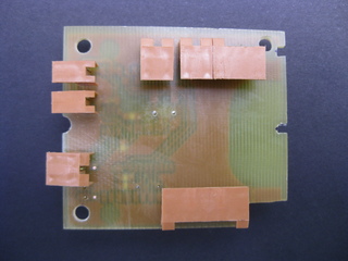
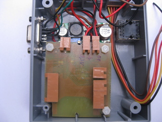
Here are some pictures constructing and assembling the device:
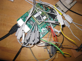


Used parts:
Maerklin Digital Connector Box 60113 aka Gleisbox
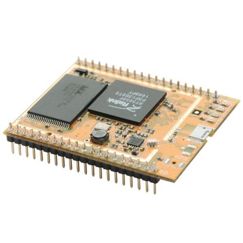
Carambola module
CAN Controller MCP2515 + Tranceiver MCP2551
DC-DC step-down converter
some ordinary electronics
Costs:
- Gleisbox 25 Euros
- Carambola 25 Euros
- PCB and MCP2515 + MCP2551 + some other electronis <10 Euros
Altogether less than 60 Euros !
A precompiled version of all software parts (modules, CAN tools and Rocrail server) can be found here.
Why using Carambola ?
This tiny module is awesome: a 320 MHz MIPS SoC with 8 MByte flash and 32 Mbyte of RAM. WLAN out of the box and plenty of reachable(!) GPIOs. 22 Euros (without VAT) is at the same level than normal OpenWrt capabable routers.
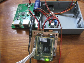
I had a look into the Maerklin box and realized that their is a lot of free space. Why not put the Carambola module into the Gleisbox ?
Power supply
The main supply of the Gleisbox is 18V DC. There is a 5V linear regulator, but the Carambola module needs 3V3. A daisy-chain 3V3 linear regulator is an option but the efficency would be bad. DC-DC converters are dirty cheap today and the efficiency is pretty well. There are a lot of LM2596 modules on ebay so I decided to take one of these.
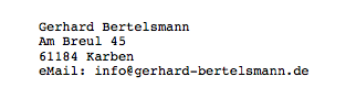
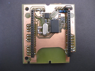
Connecting the CAN Controller to the Carambola - hardware part
The CAN-Controller MCP2515 must be connected thru SPI:
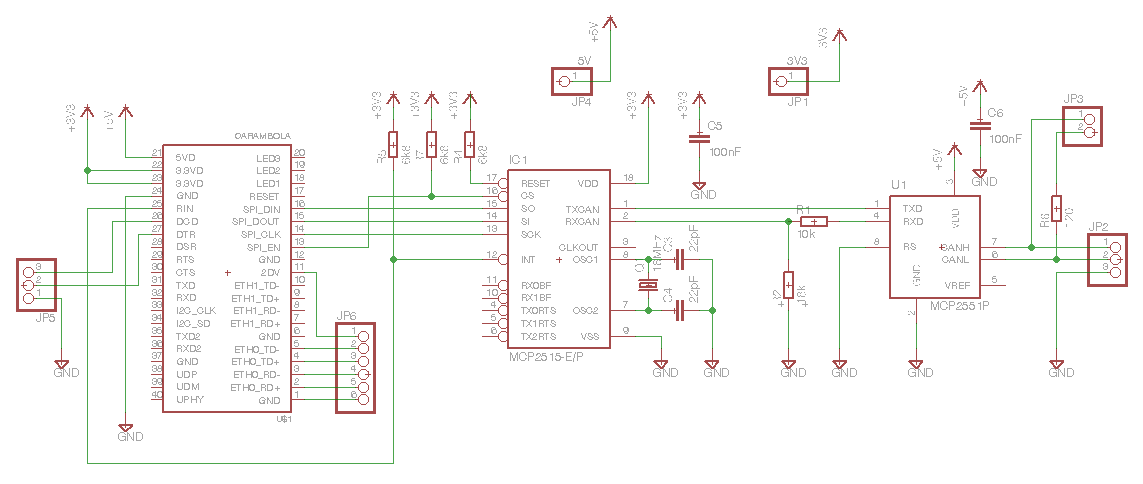
The schematic is trivial. You can find a lot examples using google. There is only one sticking point: the MCP2551 tranceiver needs 5V, but the SoC is using 3V3.So you need a voltage divider (R1/R2).
The RT3050F on the Carambola module does have a hardware SPI interface. This makes it easier to connect.
Connecting the CAN Controllers to the Carambola module - software part
OpenWrt environment
8devices.com is managing their own OpenWrt tree. They synchronize their tree with the official tree every few month.
Board definition
To use the SPI controller you have to setup the board:
--- ./target/linux/ramips/files/arch/mips/ralink/rt305x/mach-carambola.c	2012-06-11 20:43:21.724701460 +0200
+++ ./build_dir/linux-ramips_rt305x/linux-3.3.8/arch/mips/ralink/rt305x/mach-carambola.c	2012-06-29 16:05:36.663473372 +0200
@@ -22,11 +22,10 @@
 #include <asm/sizes.h>
 #include <linux/i2c.h>
 #include <linux/i2c-gpio.h>
+#include <linux/can/platform/mcp251x.h>

 #include "devices.h"

-#ifdef CONFIG_MTD_PARTITIONS
-
 #define CARAMBOLA_UBOOT_SIZE	0x030000 /*  192KB */
 #define CARAMBOLA_UBOOT_ENV	0x010000 /*   64KB */
 #define CARAMBOLA_FACTORY_SIZE	0x010000 /*   64KB */
@@ -61,15 +60,6 @@ static struct mtd_partition carambola_pa
 		.size   = CARAMBOLA_KERNEL_SIZE + CARAMBOLA_ROOTFS_SIZE,
 	}
 };
-#endif /* CONFIG_MTD_PARTITIONS */
-
-static struct physmap_flash_data carambola_flash_data = {
-#ifdef CONFIG_MTD_PARTITIONS
-	.nr_parts	= ARRAY_SIZE(carambola_partitions),
-	.parts		= carambola_partitions,
-#endif
-};
-

 static int __init carambola_register_gpiodev(void)
 {
@@ -87,6 +77,15 @@ static int __init carambola_register_gpi
        return 0;
 }

+static const struct mcp251x_platform_data mcp251x_info = {
+        .oscillator_frequency   = 16000000,
+        .board_specific_setup   = NULL,
+//        .irq_flags              = 0,
+        .power_enable           = NULL,
+        .transceiver_enable     = NULL,
+};
+
+
 static struct i2c_gpio_platform_data carambola_i2c_gpio_data = {
 	.sda_pin        = 1,
 	.scl_pin        = 2,
@@ -104,28 +103,34 @@ static struct platform_device *carambola
         &carambola_i2c_gpio
 };

-static struct spi_board_info carambola_spi_info[] = {
+static struct spi_board_info __initdata carambola_spi_info[] = {
 	{
+		.modalias	= "mcp2515",
+		.platform_data  = &mcp251x_info,
+	//	.irq		= &gpio_to_irq(14),
+		.irq		= 54,
+		.max_speed_hz	= 10000000,
+		.mode		= SPI_MODE_0,
 		.bus_num	= 0,
 		.chip_select	= 0,
-		.max_speed_hz	= 0,
-		.modalias	= "spidev",
 	}
 };

 static void __init carambola_init(void)
 {
-	rt305x_gpio_init((RT305X_GPIO_MODE_GPIO << RT305X_GPIO_MODE_UART0_SHIFT) |
+	rt305x_gpio_init((RT305X_GPIO_MODE_GPIO_UARTF << RT305X_GPIO_MODE_UART0_SHIFT) |
 			 RT305X_GPIO_MODE_I2C);
 	carambola_register_gpiodev();
 	platform_add_devices(carambola_devices, ARRAY_SIZE(carambola_devices));
-	rt305x_register_flash(0, &carambola_flash_data);

+	/* we want fixed partitions sizes for now */
+	__rt305x_register_flash(0, carambola_partitions, ARRAY_SIZE(carambola_partitions));
+
+	rt305x_register_spi(carambola_spi_info, ARRAY_SIZE(carambola_spi_info));
 	rt305x_esw_data.vlan_config = RT305X_ESW_VLAN_CONFIG_LLLLW;
 	rt305x_register_ethernet();
 	rt305x_register_wifi();
 	rt305x_register_wdt();
-	rt305x_register_spi(carambola_spi_info, ARRAY_SIZE(carambola_spi_info));
 	rt305x_register_usb();
 }
My first try connecting the CAN controller was disapointing: Initialising of the CAN controller worked but the board crashed after I tried to send a CAN frame in loopback mode. I switched to the bitbanging SPI which was working fine. Using the bitbanging SPI module has some drawbacks: the speed (only works with 800kHz - hardware SPI can use 6.66 MHz and more) and uses lots of CPU cycles. After diving into the docs and the code I realized that the RT3050 SPI only works in half duplex mode. I had setup the SPI init mode to SPI_MASTER_HALF_DUPLEX but got an error. After all I modified the spi-ramips.c to work with the MCP2515. Quite dirty hack but it works ;-)
--- ./build_dir/linux-ramips_rt305x/linux-3.3.8/drivers/spi/spi-ramips.c	2012-07-04 21:22:31.804781193 +0200
+++ own/spi/spi-ramips.c	2012-07-04 21:22:09.926020416 +0200

@@ -197,8 +197,9 @@ static inline int ramips_spi_wait_till_r
 		status = ramips_spi_read(rs, RAMIPS_SPI_STAT);
 		if ((status & SPISTAT_BUSY) == 0)
 			return 0;
-
-		udelay(1);
+	/* unnecessary delay
+	 *	udelay(1);
+	 */
 	}

 	return -ETIMEDOUT;
@@ -212,12 +213,57 @@ ramips_spi_write_read(struct spi_device
 	u8 *rx = xfer->rx_buf;
 	const u8 *tx = xfer->tx_buf;
 	int err;
+	int mcp2515_command;

 	spi_debug("%s(%d): %s %s\n", __func__, xfer->len,
 		  (tx != NULL) ? "tx" : "  ",
 		  (rx != NULL) ? "rx" : "  ");

-	if (tx) {
+	/* Ramips 3xxx half duplex workaround for mcp2515*/
+	if (tx && rx) {
+		mcp2515_command = tx[0];
+		for (count = 0; count < xfer->len; count++) {
+			/* first byte always written */
+			if ((count == 0) || (mcp2515_command & 0x40) || (mcp2515_command == 0x05) || (mcp2515_command == 0x02)) {
+				spi_debug("%s: r/w w 0x%02x\n", __func__, tx[count]);
+				ramips_spi_write(rs, RAMIPS_SPI_DATA, tx[count]);
+				ramips_spi_setbits(rs, RAMIPS_SPI_CTL, SPICTL_STARTWR);
+				err = ramips_spi_wait_till_ready(rs);
+				if (err) {
+					dev_err(&spi->dev, "TX failed, err=%d\n", err);
+					goto out;
+				}
+				*rx++=0;
+			}
+			/* mcp2515 read register instruction */
+			if ((count == 1) && (mcp2515_command == 0x03)) {
+				spi_debug("%s: r/w w 0x%02x\n", __func__, tx[count]);
+				ramips_spi_write(rs, RAMIPS_SPI_DATA, tx[count]);
+				ramips_spi_setbits(rs, RAMIPS_SPI_CTL, SPICTL_STARTWR);
+				err = ramips_spi_wait_till_ready(rs);
+				if (err) {
+					dev_err(&spi->dev, "TX failed, err=%d\n", err);
+					goto out;
+				}
+				*rx++=0;
+			}
+			if ((count > 1) && !(mcp2515_command & 0x40) && !(mcp2515_command == 0x05) && !(mcp2515_command == 0x02)) {
+				ramips_spi_setbits(rs, RAMIPS_SPI_CTL, SPICTL_STARTRD);
+				err = ramips_spi_wait_till_ready(rs);
+				if (err) {
+					dev_err(&spi->dev, "RX failed, err=%d\n", err);
+					goto out;
+				}
+				*rx++ = (u8) ramips_spi_read(rs, RAMIPS_SPI_DATA);
+				spi_debug("%s: r/w r 0x%02x\n", __func__, rx[count]);
+			}
+		}
+		goto out;
+	}
+
+
+
+	if(tx) {
 		for (count = 0; count < xfer->len; count++) {
 			spi_debug("%s: write 0x%02x\n", __func__, tx[count]);
 			ramips_spi_write(rs, RAMIPS_SPI_DATA, tx[count]);
Interrupt
Every GPIO pin can generate an interrupt with number 40 + GPIO pin number. But the init code set the max value to 48. I'm using RIN which is GPIO14 resulting in interrupt number 54. The necessary modification:
build_dir/linux-ramips_rt305x/linux-3.3.8/arch/mips/include/asm/mach-ralink/rt305x/irq.h
--- ./target/linux/ramips/files/arch/mips/include/asm/mach-ralink/rt305x/irq.h	2012-04-30 10:54:15.533108909 +0200
+++ ./build_dir/linux-ramips_rt305x/linux-3.3.8/arch/mips/include/asm/mach-ralink/rt305x/irq.h	2012-06-13 09:37:04.822406188 +0200
@@ -10,7 +10,7 @@
 #define __ASM_MACH_RALINK_RT305X_IRQ_H

 #define MIPS_CPU_IRQ_BASE	0
-#define NR_IRQS			48
+#define NR_IRQS			96

 #include_next
I have opened a OpenWrt ticket with low evidence, but I didn't get a response until now (5th July 2012).
There is a "new" MCP2515 modules which seems to work a little bit faster than the mcp251x module from the vanilla kernel. Here a comparsion of both:
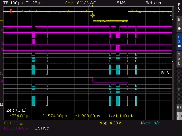
mcp251x module from vanilla kernel:
"New" mcp2515 module
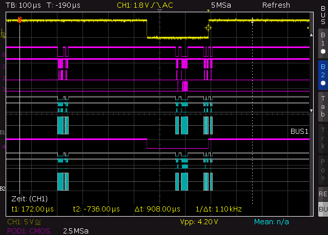
Description:
Sending a CAN frame through loopback mode with CAN clockrate 250kHz - SPI 6.66MHz
yellow -> Interrupt
pink0  -> CS
pink1  -> Clock
pink2  -> MOSI
pink3  -> MISO
grey   -> decoded MOSI
pink4  -> Interrupt
grey   -> decoded MISO
Conclusions:
- both modules loosing a lot of time (>100us) between interrupt occurence (yellow line goes down) and the CANINTF+EFLG read (the first SPI block after interrupt)
- the "new" mcp2515 module reads the RXB0 (second SPI block) a little bit earlier
- a higher SPI speed would not improve much.
Rocrail server
Please find attached a very basic script to compile Rocrail for Carambola: "rocrail_cara_compile.tar.gz"
Steps:
cd $OPENWRT_ROOT
tar zxvf rocrail_cara_compile.tar.gz

cd own
export PATH=$PATH:$OPENWRT_ROOT/staging_dir/toolchain-mipsel_r2_gcc-4.7-linaro_uClibc-0.9.33.2/bin
export STAGING_DIR=$OPENWRT_ROOT/staging_dir/toolchain-mipsel_r2_gcc-4.7-linaro_uClibc-0.9.33.2/
./auto_rocrail.sh
The binaries are found in Rocrail/unxbin.
Reduced to the max
Impressum: